")
![[Valid RSS]](http://maniek86.xyz/cmsesus/uploads/image/valid-rss-rogers.png "Validate my RSS feed")
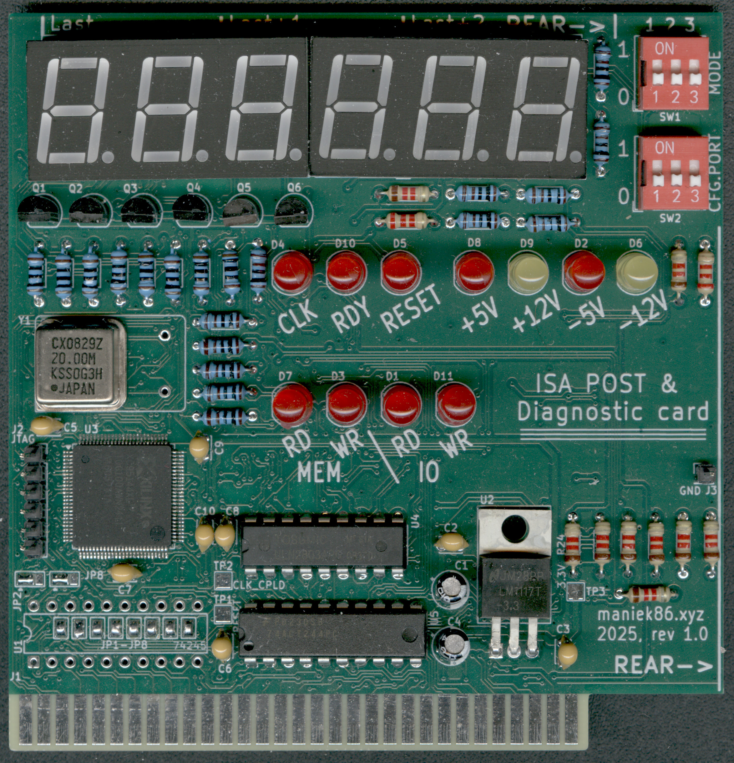
8-bit ISA debug and POST card
ISA debug post card with additional features like data/address bus analyzer, frequency measure and multi I/O POST port selection. Uses a XC95144XL CPLD as main IC.
Special thanks to PCBWay!

Special thanks to PCBWay for sponsoring this project! PCBWay is a well-known PCB prototyping and manufacturing service, providing high-quality boards and excellent customer support. I have worked with their boards in the past and can say that they are of great quality. The sponsorship also included a free quick delivery option. If you’re looking for reliable PCB prototyping and manufacturing services, I highly recommend checking them.
History
Same story as with the 8-bit ISA protoboard; I didn't have an ISA POST card. After building a prototype on a protoboard, I received sponsorship from PCBWay for proper PCBs, which allowed me to turn this card into a "full product"!
Links
Schematic and PCB design files: https://github.com/maniekx86/isa_debug_post_card
VHDL sources: https://github.com/maniekx86/isa_debug_post_card_cpld_source
Usage and features
| 1 | 2 | 3 | Mode | Description |
|---|---|---|---|---|
| - | - | POST analyzer | Default POST analyzer mode, captures last 3 POST codes | |
| ON | - | - | Data bus analyzer (D0-D7) | Data bus analyzer, displays current value on data bus D0-D7 |
| ON | - | ON | Address bus analyzer (A0-A19) | Address bus analyzer, displays current value on address bus (A0-A19) |
| - | ON | - | ISA CLK frequency counter (ISA CLK) | Frequency counter, displays frequency of ISA CLK signal |
| - | ON | ON | ISA OSC frequency counter (14.318 MHz OSC) | Frequency counter, displays frequency of OSC signal (14.318MHz) |
| ON | ON | Display current set POST port (SW2) | Displays current captured POST port set by SW2 |
- = OFF, empty = don't care
| 1 | 2 | 3 | POST Port | Notes (used by) |
|---|---|---|---|---|
| - | - | - | 80h | Standard, AT‑class (IBM AT, clones) |
| ON | - | - | 84h | Compaq models |
| - | ON | - | 90h | PS/2 Model 25 & 30 |
| ON | ON | - | 300h | Some Award BIOSes and clones |
| - | - | ON | 680h | MCA‑bus PS/2 systems |
| ON | - | ON | 60h | XT machines |
| - | ON | ON | 190h | Some PS/2 or EISA variants |
| ON | ON | ON | 378h | LPT1 (e.g., Olivetti diagnostics) |
Assembly instructions
Refer to the image below
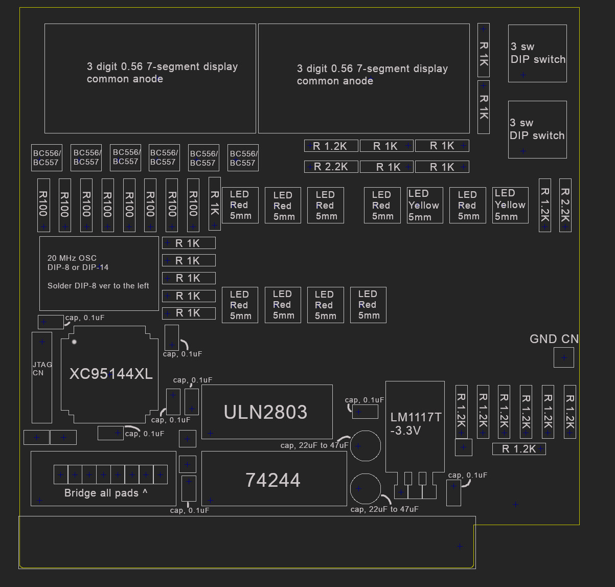
Bill of materials:
| Marking(s) | Element | Amount |
|---|---|---|
| U3 | XC95144XL | 1 |
| U4 | ULN2803 | 1 |
| U5 | 74244 | 1 |
| U2 | LM1117T-3.3V | 1 |
| Y1 | 20 MHz crystal oscillator, DIP-8 or DIP-14 | 1 |
| SW1, SW2 | DIP switch x3 | 2 |
| Q1, Q2, Q3, Q4, Q5, Q6 | BC556 or BC557 | 6 |
| U6, U7 | 3-digit 0.56 inch 7-segment display with common anode (can be found as 5631BS) | 2 |
| D1, D2, D3, D4, D5, D7, D8, D10, D11 | Red LED, 5mm | 9 |
| D6, D9 | Yellow LED, 5mm | 2 |
| C2, C3, C5, C6, C7, C8, C9, C10 | 0.1 µF capacitor | 8 |
| C1, C4 | 22 µF capacitor (doesn't need to be 22 µF, can be in range from 10 to 47 µF) | 2 |
| R1, R2, R3, R4, R7, R8, R9, R10 | 100 Ω resistor | 8 |
| R5, R6, R11, R12, R22, R23, R17, R13, R15, R14, R18, R19 | 1 KΩ resistor | 12 |
| R28, R20, R24, R30, R25, R31, R16, R21, R27 | 1.2 KΩ resistor. The used value can differ based on the desired brightness of the red LEDs | 9 |
| R29, R26 | 2.2 KΩ resistor. The used value can differ based on the desired brightness of the yellow LEDs | 2 |
| J2 | 6-pin male gold pin connector (JTAG) | 1 |
| J3 | 1-pin male gold pin connector (GND) | 1 |
Programming
Instructions and ready to upload software are available here: https://github.com/maniekx86/isa_debug_post_card_cpld_source
JTAG pinout:
| Pin | Function |
|---|---|
| 1 | TMS |
| 2 | TCK |
| 3 | GND |
| 4 | TDO |
| 5 | TDI |
| 6 | +5V |
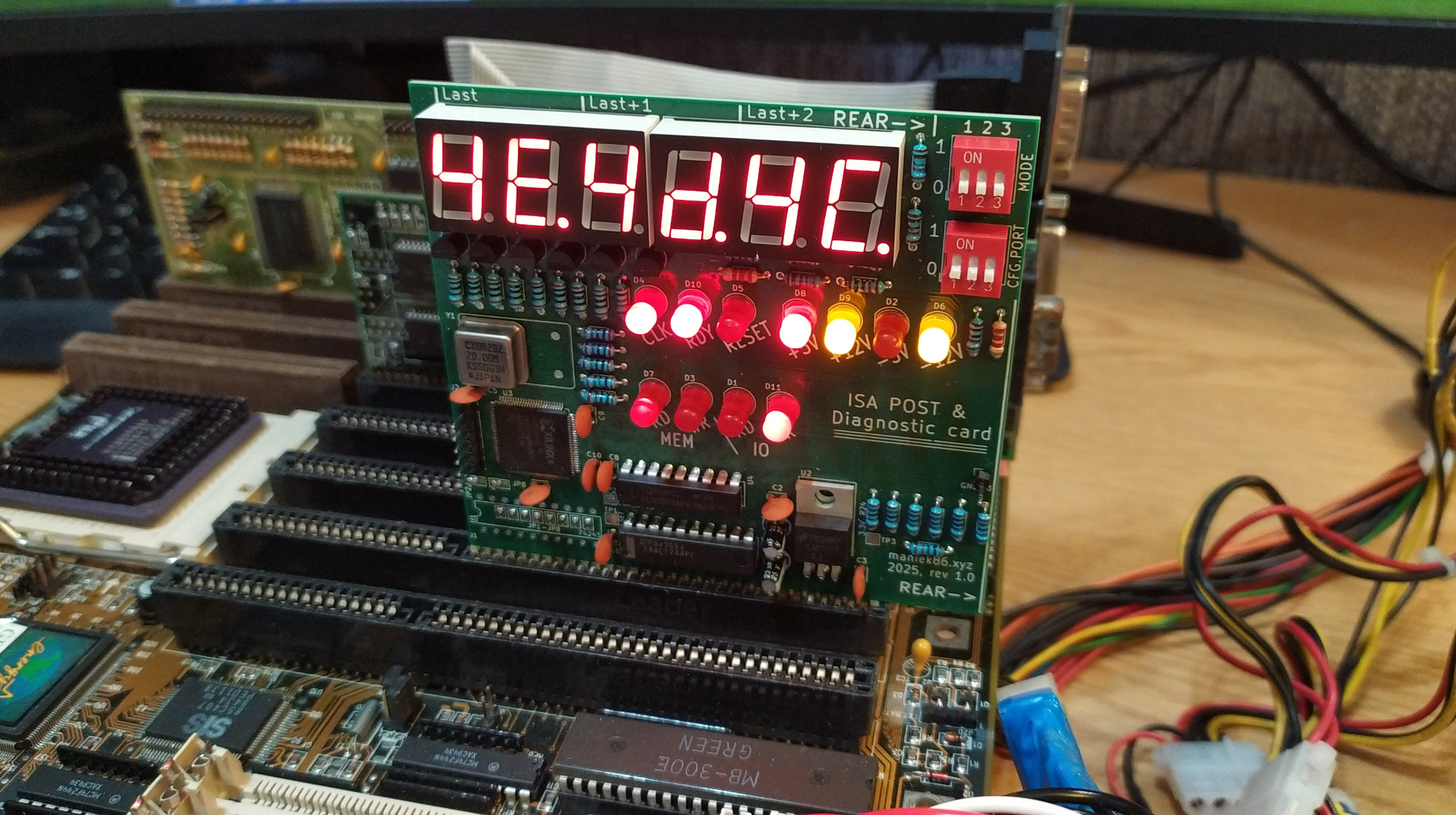
Image of finished card