

")
![[Valid RSS]](https://maniek86.xyz/cmsesus/uploads/image/valid-rss-rogers.png "Validate my RSS feed")

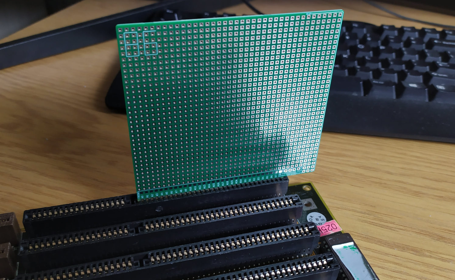
8-bit ISA protoboard
Category: Retro | Comments: 1
1336 (39*34+10) hole 8-bit ISA prototype PCB. Designed to be cheap (size 99.5mm x 99.5mm) and have as many holes as possible.
Special thanks to PCBWay!

Special thanks to PCBWay for sponsoring this project with additional PCBs! PCBWay is a well-known PCB prototyping and manufacturing service, providing high-quality boards and excellent customer support. I have worked with their boards in the past and can say that they are of great quality. For this project, I placed an order for PCBs on their platform without a problem, and as of the time of writing this, I am waiting for them to arrive. The sponsorship also included a free quick delivery option. If you’re looking for reliable PCB prototyping and manufacturing services, I highly recommend checking them.
Why?
Long time ago, I bought a cheap PCI/ISA combo POST (Power On Self Test) diagnostic card. It was a "half-scam" - it worked fine for the PCI (it showed POST codes and voltages), but for the ISA, it only showed voltages. No POST codes! I lived with that fact, but it was just annoying.
Some time forward to today: Now, with more resources and electronic engineering knowledge, I thought it would be cool to make one myself instead of buying another one. First, I wanted to make a prototype and needed a base for it, so I looked on local auction websites for "ISA protoboard" There weren't any. I looked on eBay and found something, but then I saw ridiculous prices for just a single PCB! Plus, you have to add the delivery price. I thought I could order PCBs directly from PCB manufacturers. It would be cheaper, and I could customize my design. I searched online for designs of prototype boards and found some. However, they didn't satisfy my needs. For example, some were larger than 100 mm x 100 mm, which made them more expensive. This led me to create my own design. That's how this project was born.
The POST card will be described on its own project page, which is coming soon.
The making of the project
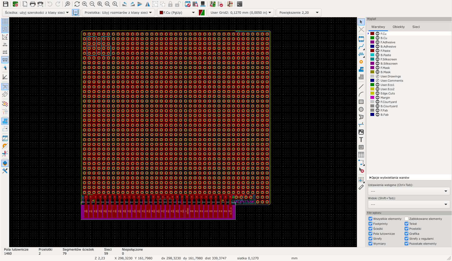
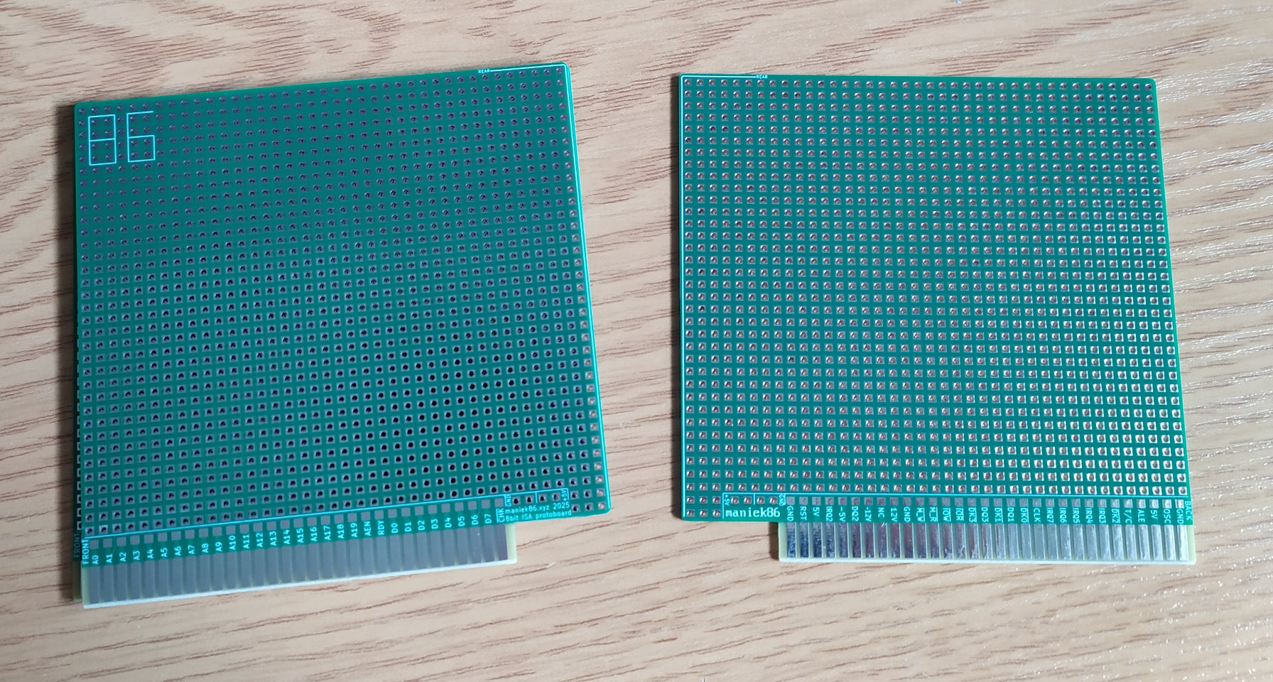
The project was easy to make (at least for me). It's just a PCB with an ISA connector and a lot of holes spaced 2.54 mm apart. For the base, I found another GitHub project with an empty ISA board outline and ISA connector - IsaTemplate from https://github.com/JayesonLS/ISA-Cards. I didn't use the schematic editor; I instantly jumped to the PCB editor to generate a grid of holes (39 x 34) using the included KiCad option to do that (I had to add custom footprints for simple holes and pads, holes were actually based on an existing jumper header footprint). Then, I drew a few traces. I also adjusted the ISA connector for a 45-degree v-cut so that, if you order my design, you can enable an edge connector with a 45-degree v-cut (A v-cut on a PCB doesn't damage the slot as much as a PCB without one does). Then, I added pads for the connections and created a silkscreen with a description of the pins and other details, such as my logo and front/back/rear markings. I personally think the design is cool. The finished PCB is optimized to be 100 mm x 100 mm, a size for which many PCB manufacturers offer discounts, and to have as many holes as possible (1,336 in total!).
I personally think that this protoboard could teach something about computer architecture. ISA is an old, simple computer bus. Its relative simplicity allows for hands-on experimentation without the overwhelming complexity of modern systems. Additionally, a protoboard makes designing and testing custom peripherals or adapting retro hardware practical, bridging the gap between theoretical knowledge and practical application.
The project is available to use by everyone on my GitHub https://github.com/maniekx86/isa_8bit_protoboard
Or you can order it directly on PCBWay: https://www.pcbway.com/project/shareproject/8_bit_ISA_prototype_board_654dd04f.html
Interessanter Beitrag.
War gerade hier gelandet und habe mir alles in Ruhe durchlesen.
Der Beitrag ist gut aufgebaut und angenehm zu lesen. Solche Inhalte sieht man selten.
Ich nehme etwas daraus lernen.
Werde bestimmt nochmal reinschauen.
Viele Grüße.
Leave a comment ▼