


")
![[Valid RSS]](http://maniek86.xyz/cmsesus/uploads/image/valid-rss-rogers.png "Validate my RSS feed")

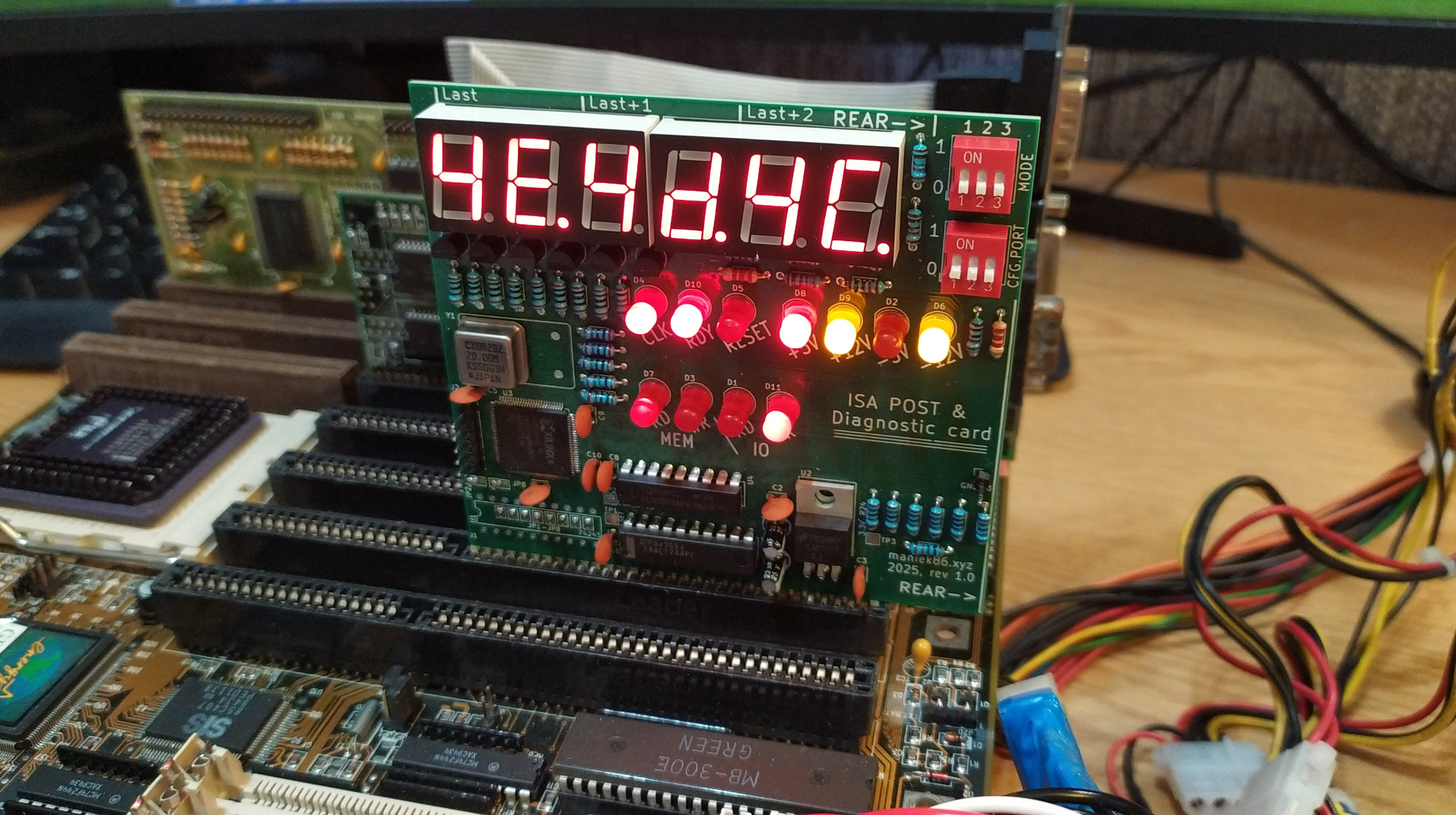
ISA POST card
Category: Retro | Comments: 0
ISA debug post card with additional features like data/address bus analyzer, frequency measure and multi I/O POST port selection. Uses a XC95144XL CPLD as main IC.
Special thanks to PCBWay!

Special thanks to PCBWay for sponsoring this project! PCBWay is a well-known PCB prototyping and manufacturing service, providing high-quality boards and excellent customer support. I have worked with their boards in the past and can say that they are of great quality. The sponsorship also included a free quick delivery option. If you’re looking for reliable PCB prototyping and manufacturing services, I highly recommend checking them.
Blog article about this project in Polish: [link]
History
Same story as with the 8-bit ISA protoboard; I didn't have an ISA POST card. After building a prototype on a protoboard (the main reason I designed and bought ISA prototype boards in the first place), I received sponsorship from PCBWay for proper PCBs. This allowed me to turn this card into a "full product"!


Prototype photos
Links
Schematic and PCB design files: https://github.com/maniekx86/isa_debug_post_card
VHDL sources: https://github.com/maniekx86/isa_debug_post_card_cpld_source
TheRetroWeb entry (thanks!): https://theretroweb.com/expansioncards/s/maniek86-isa-debug-post-card
YouTube video about this card (in Polish): https://youtu.be/HNjFFvxwhfY
Usage and features
| 1 | 2 | 3 | Mode | Description |
|---|---|---|---|---|
| - | - | POST analyzer | Default POST analyzer mode, captures last 3 POST codes | |
| ON | - | - | Data bus analyzer (D0-D7) | Data bus analyzer, displays current value on data bus D0-D7 |
| ON | - | ON | Address bus analyzer (A0-A19) | Address bus analyzer, displays current value on address bus (A0-A19) |
| - | ON | - | ISA CLK frequency counter (ISA CLK) | Frequency counter, displays frequency of ISA CLK signal |
| - | ON | ON | ISA OSC frequency counter (14.318 MHz OSC) | Frequency counter, displays frequency of OSC signal (14.318MHz) |
| ON | ON | Display current set POST port (SW2) | Displays current captured POST port set by SW2 |
- = OFF, empty = don't care
| 1 | 2 | 3 | POST Port | Notes (used by) |
|---|---|---|---|---|
| - | - | - | 80h | Standard, AT‑class (IBM AT, clones) |
| ON | - | - | 84h | Compaq models |
| - | ON | - | 90h | PS/2 Model 25 & 30 |
| ON | ON | - | 300h | Some Award BIOSes and clones |
| - | - | ON | 680h | MCA‑bus PS/2 systems |
| ON | - | ON | 60h | XT machines |
| - | ON | ON | 190h | Some PS/2 or EISA variants |
| ON | ON | ON | 378h | LPT1 (e.g., Olivetti diagnostics) |
Assembly instructions
Refer to the image below
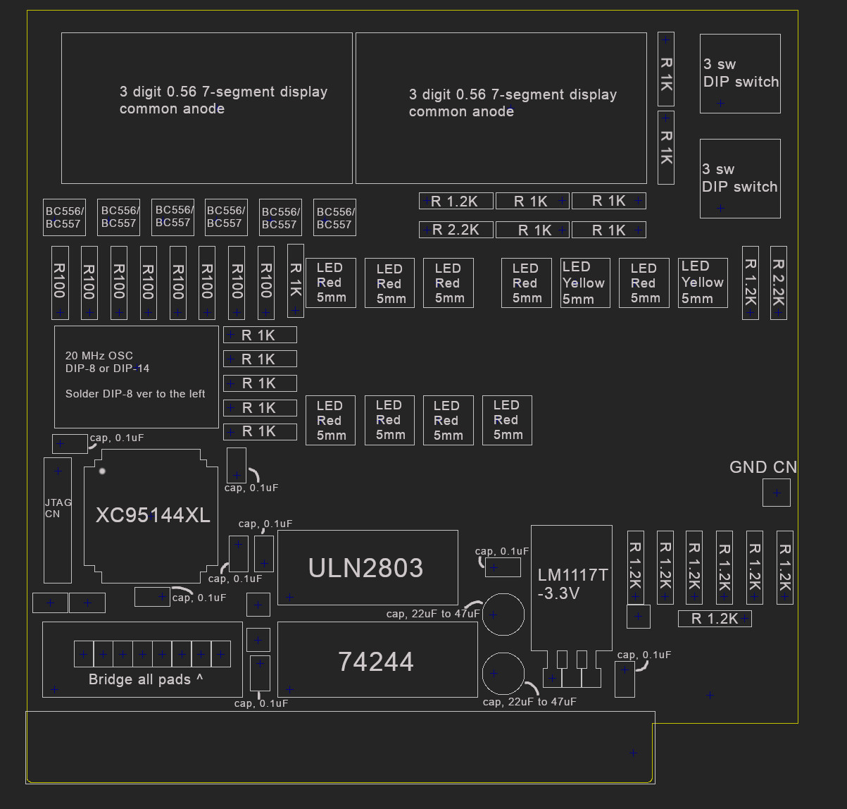
Bill of materials:
| Marking(s) | Element | Amount |
|---|---|---|
| U3 | XC95144XL | 1 |
| U4 | ULN2803 | 1 |
| U5 | 74244 | 1 |
| U2 | LM1117T-3.3V | 1 |
| Y1 | 20 MHz crystal oscillator, DIP-8 or DIP-14 | 1 |
| SW1, SW2 | DIP switch x3 | 2 |
| Q1, Q2, Q3, Q4, Q5, Q6 | BC556 or BC557 | 6 |
| U6, U7 | 3-digit 0.56 inch 7-segment display with common anode (can be found as 5631BS) | 2 |
| D1, D2, D3, D4, D5, D7, D8, D10, D11 | Red LED, 5mm | 9 |
| D6, D9 | Yellow LED, 5mm | 2 |
| C2, C3, C5, C6, C7, C8, C9, C10 | 0.1 µF capacitor | 8 |
| C1, C4 | 22 µF capacitor (doesn't need to be 22 µF, can be in range from 10 to 47 µF) | 2 |
| R1, R2, R3, R4, R7, R8, R9, R10 | 100 Ω resistor | 8 |
| R5, R6, R11, R12, R22, R23, R17, R13, R15, R14, R18, R19 | 1 KΩ resistor | 12 |
| R28, R20, R24, R30, R25, R31, R16, R21, R27 | 1.2 KΩ resistor. The used value can differ based on the desired brightness of the red LEDs | 9 |
| R29, R26 | 2.2 KΩ resistor. The used value can differ based on the desired brightness of the yellow LEDs | 2 |
| J2 | 6-pin male gold pin connector (JTAG) | 1 |
| J3 | 1-pin male gold pin connector (GND) | 1 |
Programming
Instructions and ready to upload software are available here: https://github.com/maniekx86/isa_debug_post_card_cpld_source
JTAG pinout:
| Pin | Function |
|---|---|
| 1 | TMS |
| 2 | TCK |
| 3 | GND |
| 4 | TDO |
| 5 | TDI |
| 6 | +5V |
Notes about programming
There are various ways to upload the firmware to the CPLD. The board provides a JTAG interface for this. You can use Xilinx iMPACT or openFPGALoader with a Xilinx Programming Cable, Parallel cable, or even use projects that emulate Xilinx Virtual Cable (XVC) using popular microcontrollers.
Note: The XC95144XL core is powered by 3.3V, so your JTAG cable must also operate at 3.3V.
I personally used a Raspberry Pi Pico with the xvc-pico project to upload the firmware directly from Xilinx iMPACT 14.7 using the .xsvf file. You don't need to install iMPACT, though; openFPGALoader also works. Recently (2026), I built a parallel port programmer that is less troublesome than the xvc-pico. I use it with Xilinx iMPACT, so for those with more resources I recommend this method.
For the xvc-pico project, though, I think it's the cheapest and easiest option. Below are the instructions for programming with the xvc-pico project:
- Get a Raspberry Pi Pico with the xvc-pico firmware flashed. Connect it to the POST card. Use the correct pinout as shown on the xvc-pico GitHub. Connect +5V of the card to the Pico’s VBUS pin!
- Launch the
xvc-picodaemon - Run:
openFPGALoader -c xvc-client --port 2542 --detectto detect the CPLD. If detection fails, check your connections. - Upload firmware:
- Preferred (.jed):
openFPGALoader -c xvc-client --port 2542 --file-type jed file.jed. In my case uploading .jed directly causes segmentation fault. I am not sure what causes it, but there's the second option that works fine. The openFPGALoader says it supports XC95 family? - Alternatively (.svf):
openFPGALoader -c xvc-client --port 2542 --file-type svf ./main_clean.svf. Note: Uploading via.svfis much slower (~8 minutes in my case), but it works in more cases.
- Preferred (.jed):
If openFPGAloader (with xvc-pico) has issues uploading, check the following:
- Connections: Do not use cables that are too long, as some JTAG cables have a high clock frequency which could cause problems. Additionally, make sure the programming cable is properly shielded. The reason why the JTAG pinout has ground at the middle is because I had some issues uploading firmware if it was at the side.
- The CPLD: If you order parts from AliExpress, for example, there's a small chance that the chip might be faulty or write-protected. In the first case, there's nothing you can do, but in the second case, you will need to use Xilinx iMPACT from the ISE development suite to erase the CPLD. You can download iMPACT from ISE 14.7 from the AMD website by downloading the LabTools package. Many projects (including xvc-pico) support iMPACT via the Xilinx Virtual Cable protocol, so you don't need an official programmer. Once you have it working, select Options -> Erase and check the "Override Write Protect" box. Then you can program the CPLD using openFPGALoader or just directly from iMPACT.
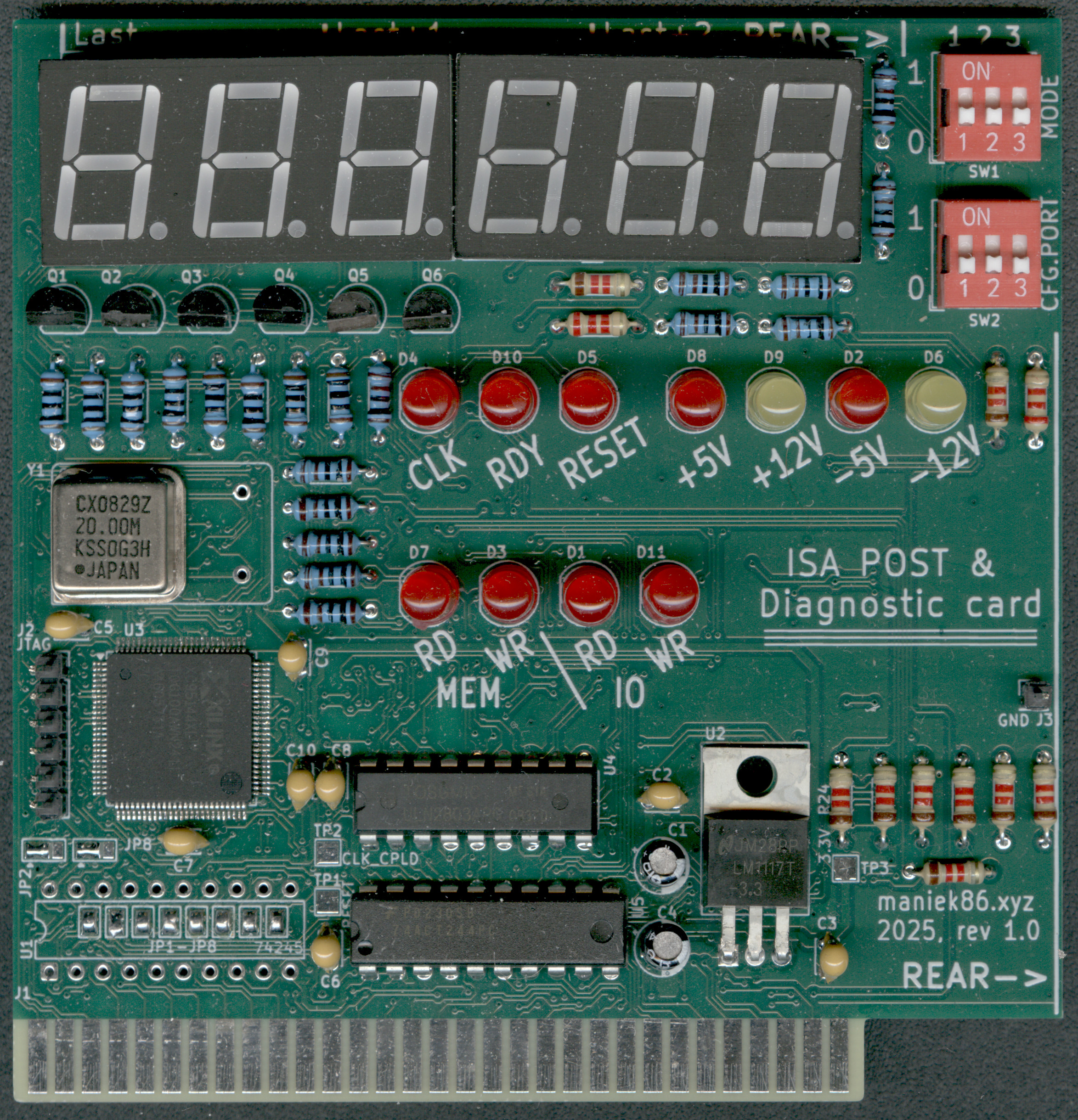
Image of finished card
Comments
No comments. Be the first one to comment!Leave a comment ▼